Theory of Rolling
Alternative Rolling Theories
In the field of metalworking, several theoretical frameworks have been developed to understand and predict the outcomes of the rolling process more accurately. These theories take into account the complexities of material deformation, friction, and the mechanical properties of both the workpiece and the rolling mill. Below are some of the alternative rolling theories that complement or enhance the basic understanding provided by classical rolling theory.
- Orowan’s Theory: Orowan's theory focuses on the calculation of roll pressure distribution and the force required for rolling. It takes into account the plastic deformation of the metal and uses the concept of a " neutral point," where the direction of friction reverses. This theory provides a more detailed analysis of the stress and strain distribution within the rolled material and helps in predicting the rolling load with greater accuracy.
- Sims’ Theory: Sims' theory extends the analysis by considering the effects of roll flattening and the elastic deformation of the rolls themselves under load. It acknowledges that rolls are not perfectly rigid and that their deformation affects the contact area between the rolls and the workpiece. Sims' theory offers improved predictions of rolling force and torque by incorporating these factors
- Alexander’s Theory: Alexander's theory further refines the calculations by including the effect of forward slip in the rolling process. Forward slip is the relative movement between the roll surface and the workpiece surface, which must be accounted for to accurately predict the rolling load and the torque required. This theory provides insights into the dynamics of the rolling process, particularly in high-speed rolling mills.
- Tselikov’s Theory: Tselikov's theory introduces a comprehensive approach that considers not only the deformation of the rolls and the workpiece but also the detailed geometry of the roll gap, including its variation along the length of the contact arc. This theory is useful for analysing the influence of roll profile and workpiece geometry on the rolling process.
- Finite Element Theory: While not a theory in the traditional sense, the Finite Element Method has become a crucial tool in the analysis of rolling processes. FEM allows for detailed simulations that can account for complex variables such as temperature gradients, material flow stress variations, and non-uniform friction conditions. This method provides a versatile and powerful means to predict the outcome of rolling processes under a wide range of conditions, offering insights that are difficult to obtain through analytical theories alone.
Roll Bite Mechanics
Equation for Contact Length
For flat rolling, where the rolls are assumed to be rigid and the deformation of rolls due to pressure is neglected, the contact length can be approximated using the following formula:
\[ \mathrm{L}=\sqrt{\mathrm{R} \cdot \Delta \mathrm{h}}\]Where: \(\mathrm{L}\) is the contact length, \(\mathrm{R}\) is the radius of the work roll, and \(\Delta\mathrm{h}\) is the difference in the height of material before and after plastic deformation (i.e. the reduction in thickness or draft).
Conservation of Mass in the Roll bite
In the roll bite, the rolled material is subjected to compressive forces that reduce its thickness and increase its length (and possibly its width). The mass flow principle here ensures that the mass entering the roll bite per unit time is equal to the mass exiting it, assuming a steady-state process without any addition or loss of material.
The mass flow equation, can be formulated based on the conservation of mass as follows:
\[ \rho \cdot \mathrm{A}_{\text {in }} \cdot v_{\text {in }}=\rho \cdot \mathrm{A}_{\text {out }} \cdot v_{\text {out }} \]Assuming the density and width remain constant through the roll bite, the equation reduces to,
\[\mathrm{h}_{\text {in }} \cdot v_{\text {in }}=\mathrm{h}_{\text {out }} \cdot v_{\text {out }} \]Forward Slip
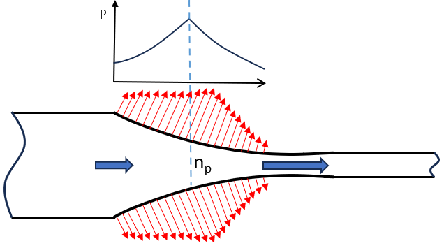
From the conversation of mass, the strip enters with a velocity \(v_{\text{in}}\) and exits with a velocity \(v_{\text{out}}\) where the speed of the roll, \(v_{\text{roll}}\), is somewhere between the two. Due to the metal undergoing deformation as it passes through the roll bite, there is point where the roll speed matches the strip speed which is known as the neutral point. The forward slip, which is often given in terms of the relative velocity, is defined as:
\[f=\frac{v_{\text{out}} - v_{\text{roll}}}{v_{\text{roll}}} \]The concept forward slip is important for a number of reasons
- Friction conditions: The forward slip is dirrectly correlated to the friction conditions in the roll gap. There are numerous articles that have used this knowledge to order to better under that friction conditions.
- Surface Defects: Accurate determination on the forward slip will help minimise scratches that occur on the bottom surface of the sheet due to a mismatch in the roller table and strip speed
- Rolling Force and Torque Calculations: Understanding the forward slip is crucial for accurately calculating the rolling force and torque required by the mill motors. It affects the surface quality, thickness tolerances, and material properties.
Deformed Roll Radius
The deformed roll radius during rolling is a critical concept in understanding and modelling the rolling process, especially in heavy plate and sheet rolling where the forces involved can lead to significant deformation of the rolls themselves. This deformation affects the contact area between the roll and the material, influencing the material's thickness reduction and the rolling force required. The concept of roll flattening or elastic deformation of rolls is crucial for accurately predicting the rolling process outcomes. Roll deformation or roll flattening refers to the elastic deformation of the rolls under the high load applied during the rolling process. The actual radius of the roll in contact with the material becomes effectively larger than the nominal radius of the roll due to this deformation.
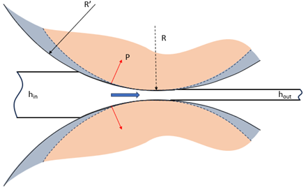
The calculation of the deformed roll radius involves complex elasticity theory and requires considering the distribution of stress and strain across the roll body. A simplified approach to estimate the effective roll radius under load involves empirical formulas or finite element analysis (FEA) models that take into account the rolling force, roll material properties, and initial roll dimensions.
One of the commonly used empirical equation for roll flattening in rolling, which gives a simplified estimate of the deformed roll radius is provided by Hitchcock who showed that the deformed roll radius, \(R^{\prime}\), is given by:
\[ R^{\prime}=R\left[1+\frac{c P}{\left(h_{\text {in }}-h_{\text {out }}\right)}\right] \]where \(R\) is the nominal roll radius, \(P\) is the rolling force per unit width, and \(c\) is known as the Hitchcock constant guven by
\[ c=\frac{16(1-\nu_{roll}^2)}{\pi E_{roll}} \]where \(\nu\) is Poisson's coefficient and \(\text{E}\) is the Young's modulus for the roll.
Understanding and compensating for the roll deformation is critical for:
- Control of Final Product Dimensions: Accurate predictions of gauge reduction
- Rolling Force Calculations: Necessary for designing rolling mills and setting process parameters
- Roll Life and Maintenance: Excessive deformation can lead to roll damage and require more frequent maintenance
Rolling Load and Torque
A common approach to determining the rolling load and torque involves analysing the balance of forces applied to a small section of the material as it passes through the roll bite. This method is rooted in the principles of plastic deformation and mechanics, aiming to ensure that the work done on the material by the rolling process is accurately accounted for. The approach considers the static equilibrium of the forces in a slab of metal (signified in green) undergoing plastic deformation between the rolls, as shown in the figure below:
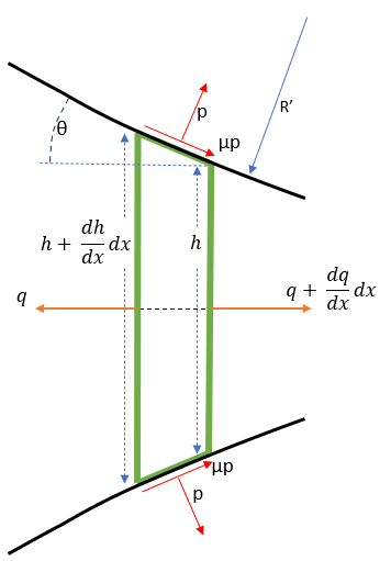
By balencing the forces in the horizontal x-direction and assuming homogenious compression (where vertical planes remain planes) the resulting equation is given:
\[ \frac{dq}{dx} + p\frac{dh}{dx} \pm 2 \mu p=0 \]where slipping friction is assumed between the roll and metal being rolled (\(\tau =\mu p \)). The (\(\pm \)) sign indicates that the equation above describes the conditions of equilibrium between the neatural point and the entry as well as between the neutral point an the exit. Thus, there are two independent first-order differential equations.
In order to solve these equations it is necessary to eliminate one of the unknowns either \(\mathrm{q} \) or \(\mathrm{p} \). This is accomplished by using the Hube-Mises criterion of plastic flow, relating the stress components in the direction of rolling and perpendicular to it to the metal's flow strength:
\[ \mathrm{q} + \mathrm{p} = 2 \mathrm{k} \]where \(\mathrm{k} \) is the plain-strain flow stress.
In this work, the ordinary differential equations are combined with the Huber-Mises condition and are solved numerically. The solution is obtained iteratively due to the fact that \(\mathrm{q} \), \(\mathrm{p} \) and \(\mathrm{h} \) are all dependent on \( R^{\prime} \) while \(\mathrm{k} \) is a function of strain, strain-rate and temperature of the strip material as it traverses the roll bite.
The specific roll force per unit width P is determined by integrating \(\mathrm{p} \), along the arc of contact from the entry to the exit:
\[ \mathrm{P} = R^{\prime} \int_{0}^{\theta} \mathrm{p}(\theta) \,d\theta \]Normal Pressure Distribution
The friction hill, as it may be referred to, is the normal pressure distribution in the roll surface due to the contact pressure over the contact arc. The figure below illustrates the neutral point and normal pressure distribution over the contact arc: